Understanding PHD2 Parameters


|
|
Esta mensagem foi atualizada em .
Some words to understand guiding with PHD2. It is not a complete tutorial. It is only some empirical observations.
1. The main goal of guiding is correct drift of target star caused by Periodic Error of mounting and small polar misalignment. 2. The accuracy of the result of guiding depends from resolution (arc second per pixel) of main telescope, resolution of guiding set, intensity of refraction of atmosphere. Note: a set of parameters that always work fine can doesn’t work if the refraction is very high. 3. What the best values ? Each case is a unique case. What works fine for one set of equipments can doesn’t work for others. 4. How to set and test the values ? a) The best values will cause minor corrections, since any correction will be a drift of the star to correct the actual drift. b) The graphic of PHD can help to analyze the performance of values, but it actually doesn’t represent the truth. Some values cause a good appearance only because the pulses aren’t sent to mounting. Therefore we don’t see the movement of corrections. It seems that there isn’t drift, but the image from main camera shows that there was many. 5. To begin the parameterization: a) In tab Camera set the pixel size of guiding camera. Ex: mine ASI120MC has 3.75. You can use or not dark frames. Read the pop up help window when the mouse is over the control. b) In tab Mount set force calibration and enable guide output. Set Hysteresis to 10.00, Aggression to 50.00, Minimum Move to 0.10, Declination Algorithm to Resist Switch and Minimum Move to 1.00. For calibration steps use the values from calculate bottom. Set Guide Mode box to Auto. Hysteresis: resource to use the priors correction pulse values to calculate the current value. It can smooth the bad influence of sudden refraction. Aggression: intensity (gain) to produce the pulse correction. It depends from mechanical characteristics of the mounting and how heavy is optical system on it. If it is very high you will have oscillation: over correction to one side and thus over correction to other side. Minimum move: all movement of star below this value will be ignored to produce pulse correction. It helps to smooth the bad interference of refraction. High values can create false graphic where no drift is seen, despite they are present. Declination Algorithm: how PHD will create pulse correction to DEC drift. As all mounting has backslash to reverse the movement (North-South and vice-versa), Resist to Switch will help to reduce this switching. All drift above the minimum value will cause pulse correction. The best value depends from quality of polar alignment. It is better lower intensity of correction than great intensity. Remember that all correction cause some drift to correct the actual drift. c) In tab Guiding set Star mass change detection to 50. This set is very important. It will say to PHD the center of a star. PHD will measure the drift using this center. If your guiding system has much accuracy (resolution - arc second per pixel) it will see distortion from refraction. The star will change with intensity its shape, that will cause different center and thus false drift that will generate pulse of correction or PHD error message of Mass. Ex: my system has more resolution than my main camera Canon. ASI120MC with OAG see things that the resolution of my Canon can not see. My Canon has 0.65 arc second/pixel and my ASI120MC has 0,45 arc second/pixel. So, I must set this parameter to 0.70. Otherwise I will have constant PHD Mass error and interruption of guiding task during this period. You can see these distortions with resource from menu View > Display star profile graphic. note: sometimes my atmosphere refraction is so high that I can not find any good values to guiding. The guiding star not only change the shape, it changes the position with much intensity. When this happens … I go to my bed ! The others parameters in this tab isn’t important. Let them as they are. d) In tab Global set the focal length of your optical guiding system. You can use the link to find it: http://www.12dstring.me.uk/fov.htm - Attention: use the data of your guiding camera. You can use or not dark frames. If you don’t use it, you can set noise reduction to smooth the view of the star. I use noise = 3x3. The others parameters aren’t important to a common guiding. 6. Fine adjustment (do it only if the atmosphere refraction isn’t high – You can see these distortions with resource from menu View > Display star profile graphic: a) For RA: See the graphic (menu View > Display graphic). Set it to arc second view. Set the box corrections to see the RA pulses generated. Adjust the aggression to have the minor quantity of pulses and to have the best similar small movement of RA drift line above and below the zero line value. If the pulses are only above or below increase the value. Wait for the total time of the mechanical gear cicle of your mouting. Ex: my NEQ6 has around 7.5 minutes. If you have some peak during this time caused by mechanical characteristics of your mounting, adjust the minimum move and/or hysteresis to smooth it. Minimum move can help to smooth drift from polar alignment error. Remember: it is best lower intensity corrections than large ones. Do not worry if the PHD will send many pulse corrections. Remember: the RA motor will always in movement. The pulse correction will only accelerate or decelerate this movement. BE patient, be patient and be patient. You can waste all the night to find the best values. b) For DEC: See the graphic. Set the box corrections to see the DEC pulses generated. Adjust the minimum quantity of pulses to obtain the most linear line of DEC drift. It is very important that you haven’t much commutation of correction from North to South or vice-versa. Remember: all mounting has problem of backslash, and the DEC motor is always off. It is not like RA motor. If you have the majority correction to one direction, and sometimes appears some peak to another direction, try to set the guide mode only to the direction of major drift: North or South. Ignore the peak to another direction. You can loose some frames, but all others will be ok. DEC correction has source mainly by bad polar alignment. Some atmosphere refraction can cause false information of DEC drift, also. 7. Are the parameters ok for my optical system ? You can have some idea by comparison the peak to peak arc second drift of your guiding (the PHD graphic will show it) with the resolution (arc second/pixel) of your main camera. Ex: my system has guiding accuracy of 0.45 arc second/pixel and my Canon has 0.65 arc second/pixel. So, if peak to peak is around 1 arc second … my Canon will not see this drift. If peak to peak is around 1.5 arc second or more … my Canon will see, and the stars will show some distortion. I use OAG with ASI120MC, OTA GSO 305 mm on NEQ6 mounting and Canon 1100D. To obtain better control of pulse correction I use the EQMOD platform, that has many others controls. My resolution of guiding is very high. So my photo below of PHD and EQMOD isn’t a universal example. EQMOD is set to 100 % of PHD2 correction pulse for RA, and only 15 % for DEC (my PHD2 version with Resist Switch option hasn’t control for DEC aggression) . And as my system is very heavy I set the percentual of sideral speed to 0.65 for RA and 0.75 for DEC. These parameters are different from time pulse from PHD2. They adjust the speed of movement of the mouting during the time pulse of PHD2. I need it hight because of inertia of my heavy optical set. 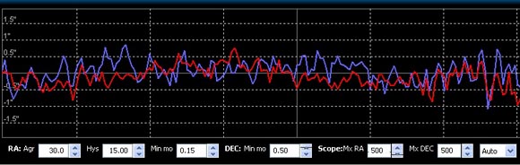 notes: 1) I did reference for "atmosphereric refraction" as source of "false drift". You can add "or vibration" caused by wind or any other source. 2) some imperfection of gear can cause some peak in the drift graphic. Usually you can identify it because they will be simultaneous on RA and DEC. I had one at the end of the first graphyc. Don't worry with it. Use Hysteris or Minimum Motion to reduce that interference for PHD2 correction pulse. 3) the second photo was did with ASI120MC - OAG and PHD version 1. 4) as I use the EQMOD platform, I set to see dx and dy, since EQMOD already shows the actual RA and DEC pulses sent to mounting. The graphic is set to arc second, although. 5) The actual measure of arc second drift is more important than Osc Index and RMS values. 6) after find the best values, you can use them forever. Only some small adjustment will be necessary because of atmosphere quality. *********************************************** Interference from refracton at 2016, May 2  PHD and EQMO parameters with quite good seeing at 2016, May 2  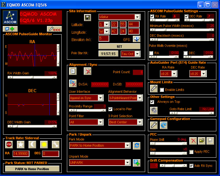
GSO 305 mm
NEQ6 Pro - Roda 5 Filtros Manual Guia: OAG TSOAG9T2 - ASI120MC Cannon EOS T3 - QHY163M ASI120MC, DSI-1 Meade e SPC880 |
«
Retornar para Guiamento & Afins
|
1 visualização|%1 visualizações
| Free forum by Nabble | Nabble® |